|


GL140
Cissoko
| Quantity: | |
|---|---|
The GL140 is a high-performance Hydraulic Lifting Valve for Dump Trucks, engineered to meet the rigorous demands of heavy-duty applications. With an impressive maximum peak pressure of 350 bar and a rated flow of 140 L/min, this valve ensures powerful and efficient lifting and lowering of dump bodies. It operates reliably across a wide working temperature range of -25 to 80°C and is compatible with anti-wear hydraulic oil. The GL140 integrates multiple functional valves—including directional control and pressure regulation—into a compact, robust unit. Complying with stringent safety standards, it delivers dependable performance for mining trucks, heavy-duty tippers, and various engineering machinery, making it a cornerstone of a robust dump truck hydraulic system.
Three-way multi-functional proportional control: The valve body has three functions: Raise, Hold, and Lower. It supports pneumatic proportional adjustment, allowing the driver to precisely control the descent speed of the carriage ( slow and fast descent can be freely switched ) via the pneumatic valve handle in the cab, effectively eliminating return oil shock.
Integrated Safety Matrix: The valve body integrates a main safety relief valve and a load check valve . Even if the vehicle experiences an unexpected gas outage or a sudden pump failure, the check valve can firmly lock the oil circuit, preventing the cargo box from sinking unexpectedly and ensuring all-weather operational safety.
Flexible installation in both directions: The valve body is specially designed with a low profile and lightweight compact design. It supports both direct mounting with the tank flange integrated (Tank-Mount) to simplify hose layout, and external mounting via side mounting holes on the chassis beam (Chassis-Mount) .
Leak-proof and long service life: The valve core is hardened with chrome/nickel plating and the sturdy ductile iron shell has extremely high fatigue resistance, effectively reducing system heat generation and internal oil leakage in the valve body under high-frequency operation.
| Parameter | Specification |
|---|---|
| Product Type | Hydraulic Tipping Valve |
| Model Number | DM14 |
| Maximum Peak Pressure | 350 bar |
| Rated Flow | 140 L/min |
| Maximum Pressure | 400 bar |
| Working Temperature | -25 to 80°C |
| Working Medium | Anti-wear hydraulic oil |
Applications
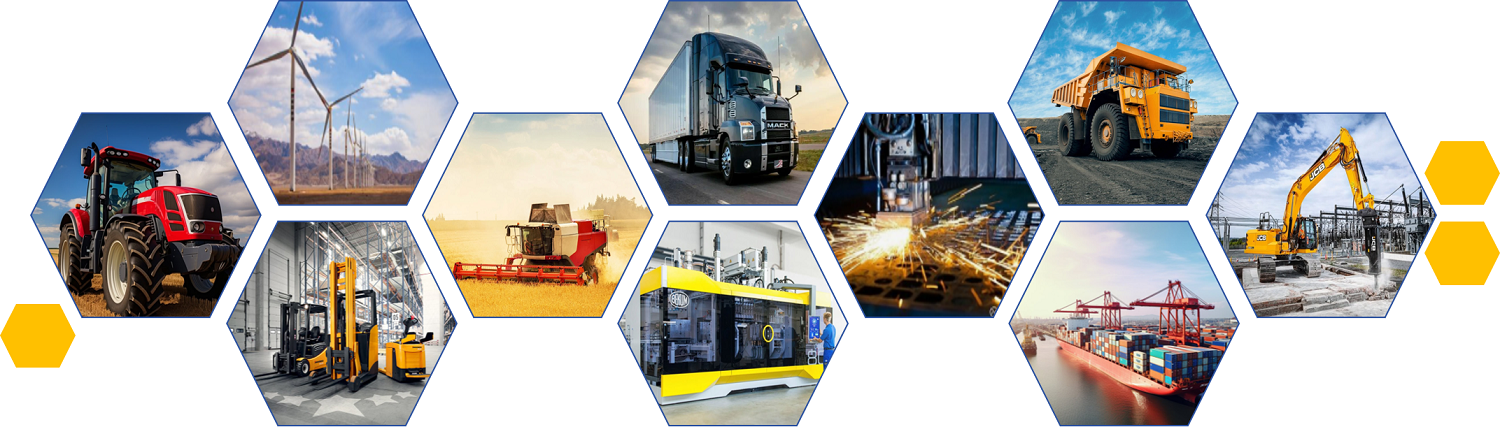
Medium and large dump trucks and semi-trailers: As the core control valve of the on-board wet hydraulic kit, it is used to drive the multi-section front-mounted telescopic hydraulic cylinder.
Bulk and heavy-duty transportation in engineering: occasions where frequent unloading of sand, gravel, minerals, and urban construction waste is required, and where the single unloading efficiency (140L/min large throughput) and slow descent safety requirements are extremely high.
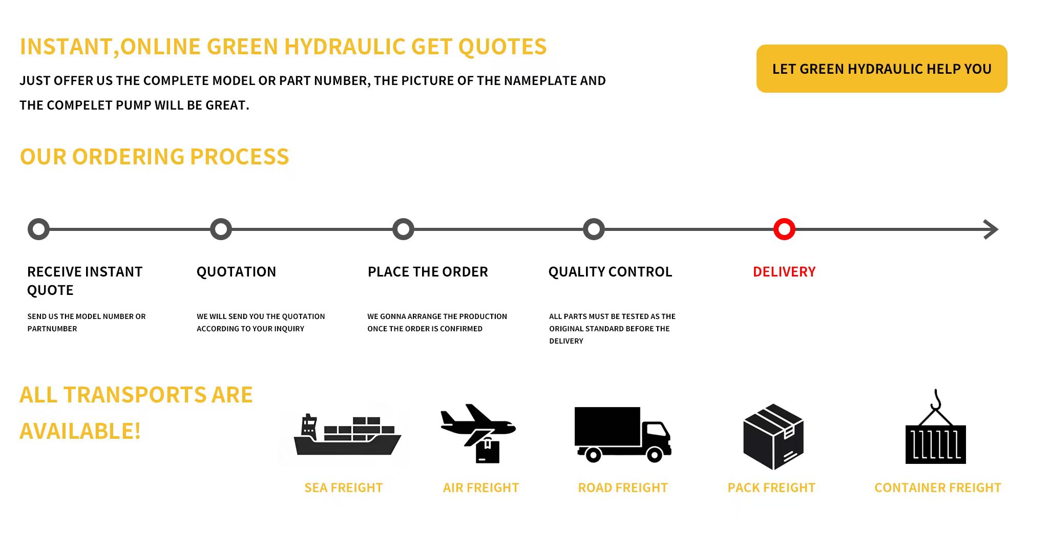
GL140 Hydraullic Valve for Tipper are typically packaged securely to prevent damage during transit. The packaging includes:
Protective Wrapping: To safeguard the pump from environmental damage.
Custom Crates: For larger, heavier pumps, ensuring safe handling.
Documentation: Includes installation, maintenance instructions, and warranty details.
Delivery time depends on the model, customizations, and location but typically ranges from 2 to 6 weeks from the order date.
A: The flow rate directly determines the lifting speed of the cargo box . 140 L/min is considered a medium to high flow rate design (commonly used in front-mounted multi-section hydraulic cylinder systems).
Impact: It allows dump trucks to quickly complete the lifting action at rated speed , significantly shortening the unloading time per operation. If a valve with a smaller flow rate (such as the 80L series) is used, the lifting speed will be noticeably slower.
A: These numbers represent the factory-set relief pressure (in Bar) for that particular model . For example, the safety relief valve of the DM140-175 is factory-set to 175 Bar (approximately 17.5 MPa) [16].
Replacement Recommendation: Do not blindly replace parts directly . If the original vehicle requires 195 Bar, replacing it with 175 Bar will cause premature pressure release when lifting heavy objects and insufficient lifting power under heavy loads; conversely, if the pressure is too high, it may cause overload damage to the cylinders, hoses, or hydraulic pump. The design pressure of the original vehicle system must be checked before replacement.
A: This depends on its pneumatic proportioning design .
Principle: The valve core inside the valve body is driven by pneumatic pressure (usually 0.6–1.0 MPa). When the driver fine-tunes the pneumatic control handle in the cab, the air pressure input to the lifting valve is relatively low, the valve opening is only slightly open, the return oil volume is small, and the truck bed descends slowly; when the handle is pushed all the way down, the air pressure is at its maximum, the valve opening is fully open, the return oil volume is large, and the truck bed descends rapidly.
A: It's highly likely. The automatic slippage during a stop (commonly known as "arm drop" or "cylinder slippage") is primarily caused by internal leakage in the lifting valve , after ruling out internal leaks in the cylinder itself and external pipeline leaks .
Main cause: The surface of the load-holding check valve or cone valve core inside the valve is contaminated with hydraulic oil, making it sticky with iron filings or sand particles, or worn and grooved. This prevents a perfect seal under high pressure, resulting in oil leakage and pressure loss. Usually, it requires cleaning the valve core or replacing the internal seals/repair kit.
A: Both methods have their advantages and disadvantages, depending on the vehicle's chassis space and piping design.
Direct tank mounting (flange connection): The valve is directly locked onto the tank. Advantages include reduced main return hoses, lower risk of leaks, and improved overall integrity.
External chassis mounting (fixed to the main beam): The valve is fixed to the main beam via brackets. The advantages are more flexible installation location, not limited by the shape of the oil tank, and greater operating space when maintaining the valve or replacing pipelines later.
Yes, we support OEM and customization, including nameplate, packaging, and specific performance requirements. Send us your drawings or specifications for evaluation.
GL-H1220-AO-Integral Shunt Combination Valve are manufactured in compliance with international standards, ensuring high performance and reliability:
ISO 9001: Certified for quality management systems.
CE Certification: Ensures compliance with European safety, health, and environmental protection standards.
RoHS Compliance: Ensures the Valve does not contain hazardous materials.
Factory Testing: Every valve is rigorously tested for performance, pressure, and leak integrity before shipping.
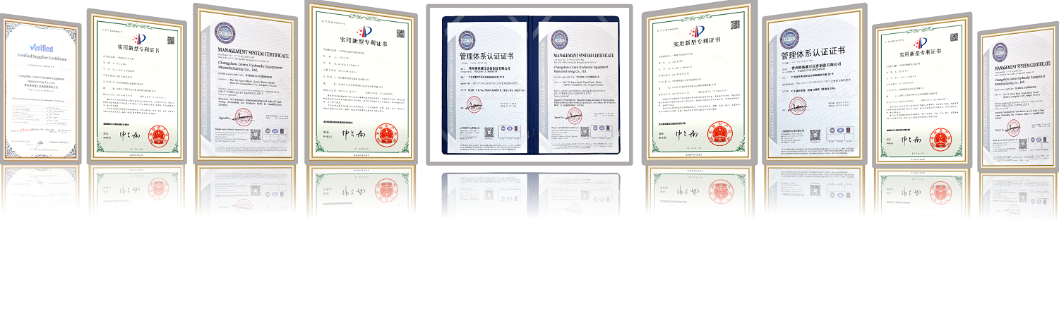
1.What's our advantages?
Factory established in 2005;
With a great deal of production experience;
80+ employees become the professional team;
Constant updated ERP system ensure efficiency of work;
Sophisticated equipment ehanced the accuracy of products;
Professional salesmen provide the greast service;
With a large number of famous customers all over the world;
Great after-sales service;
With the long term cooperation with famous logistics and express company in China,provide the better goods service.
Small order/sample order,full payment in advance; Big orders send the first payment 30% before the production,and the balance before shippment.We'll show the photos of the products and packages before delivery.
Of course we can. Just send me your logo we can make it for you.
America(40.5%):USA, Canada, Argentina, Brazil
Europe(30.8%):Italy,Germany,England,Holland,Spain,Swiss,Finland,Russia,Poland.
Asia(23.5%):Korea,singapore,India,Turkey,Vietnam,Saudi Arabia,Syria, Israel,Lebanon.
Others(5.8%).
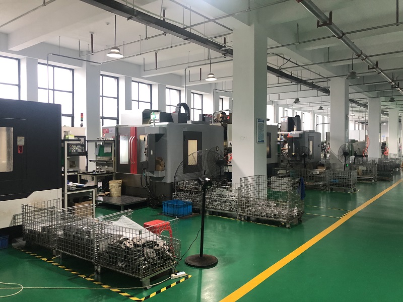
The Cissoko hydraulic pump manufacturing facility is a specialized industrial plant that focuses on producing hydraulic pumps and related components. These factories are equipped with advanced machinery and technology to fabricate high-quality pumps designed for a wide range of applications, from heavy equipment and machinery to automotive and industrial systems.
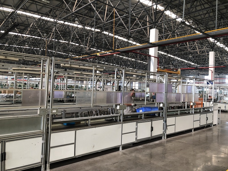
The production process typically involves precision engineering, where raw materials like metals and alloys are processed into pump components such as gears, pistons, cylinders, and seals. These parts are then assembled into fully functional hydraulic pumps, which are tested for performance and quality control to ensure reliability, efficiency, and durability under various working conditions.
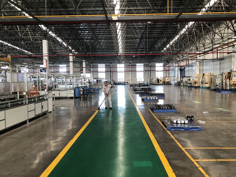
Cissoko Hydraulic's manufacturing facilities for hydraulic pumps maintain stringent quality standards, often adhering to international certifications, to meet the expectations of customers in industries such as construction, agriculture, automotive, and manufacturing.
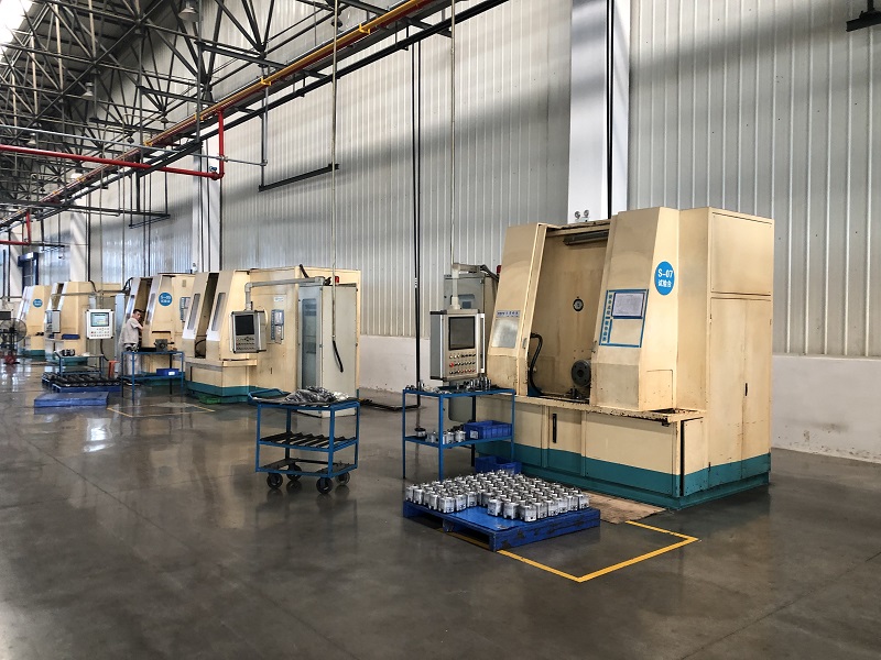
All hydraulic pumps produced by Cissoko Hydraulic have undergone compliance testing, ensuring their quality and reliability.
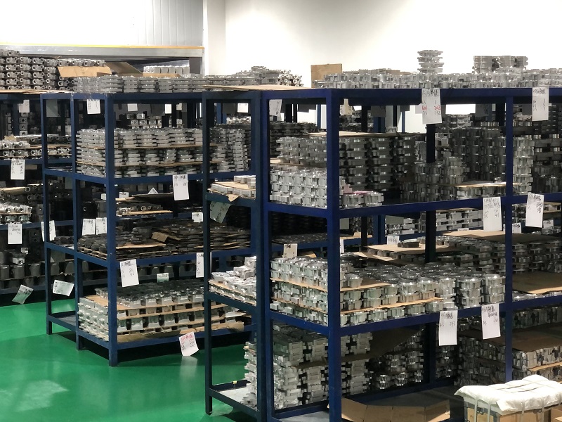
To meet the diverse needs of different industries, the Cissoko hydraulic offer customization options, such as specialized seals, materials, and pump configurations. These facilities often work closely with engineering teams to develop tailored solutions for specific applications, from high-pressure systems to low-flow, high-efficiency pumps.
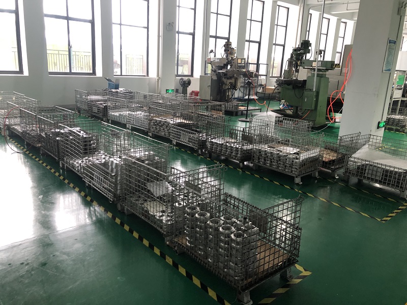
Each pump undergoes a rigorous quality control process, where pressure tests and performance assessments are conducted to ensure that the pumps meet the required standards for flow rate, pressure capacity, and durability.