
Views: 0 Author: CISSOKO Publish Time: 2016-04-20 Origin: Site


Matching the PTO, hydraulic pump and hydraulic cylinder for a dump truck follows a core sequence: determine pressure based on load, flow rate based on speed, and match ports to standard specifications, followed by verification of mounting dimensions and control logic.
First, define the fully loaded weight of the truck body and the required lifting time to back-calculate the thrust and flow demand of the hydraulic cylinder. Then work backwards to select pump displacement and PTO torque. Finally, verify the flange type, rotation direction and rotational speed. The process is broken down into three steps below.
Define the load characteristics of the hydraulic cylinder and prime mover conditions
Perform calculation for pressure, flow rate and power matching
Check the stability of the system under extreme working conditions
The matching of hydraulic pumps and hydraulic cylinders shall follow systematic design principles:
Clarify the load characteristics of the hydraulic cylinder (e.g. thrust and speed requirements) and operating mode (continuous / intermittent), and define the power and speed parameters of the prime mover. This serves as the foundation for matching.
The core lies in pressure and flow matching. Determine the rated pressure of the pump based on the maximum working pressure required by the hydraulic cylinder (a safety factor of 1.1 shall be adopted). Calculate the required flow rate according to the moving speed of the cylinder to select the pump displacement. Meanwhile, verify whether the power of the prime mover can meet the system requirements.
Check the stability of the system under extreme working conditions, and confirm that parameters such as pressure shock and temperature rise are within allowable limits. Add buffer devices or cooling systems when necessary.
These three steps form a complete logical chain from requirement definition to implementation in hydraulic system design, and are critical to ensuring reliable system operation.
Mismatching Power Take-Off (PTO) and Hydraulic Pump isn't just an inefficiency. It is a leading cause of sheared shafts, blown seals, and voided warranties in work trucks. Specifying the right combination requires working backward from the equipment’s demand to the truck’s transmission capabilities. You must understand precise flow and pressure requirements before opening a catalog. Ignoring these technical constraints quickly compromises system integrity and safety. Establishing a rigid engineering framework for mating these components ensures reliable power delivery. This careful planning maintains safety compliance and eliminates costly equipment downtime. We will walk you through exactly how to match these complex systems. You will learn to calculate flow rates, determine correct speed ratios, and verify torque limits. We also cover crucial installation details like shaft rotation and mounting clearances to guarantee a flawless integration.
When selecting a hydraulic cylinder, calculate the thrust first, and then determine the cylinder diameter and stroke.
Calculate based on the load and lifting angle. The formula is F = P × A. The larger the cylinder diameter, the greater the thrust, but the pressure is also higher. In engineering, a simplified formula is used: Thrust (ton-force) = 3.14 × Pressure (MPa) × (Cylinder diameter mm ÷ 2)² ÷ 10,000.
The stroke is determined by the lifting height of the vehicle body. When the installation space is limited, choose a front-mounted top or mid-mounted top hydraulic cylinder. The cylinder diameter is selected based on the load, and reference specifications such as the 180×4280 hydraulic cylinder are suitable for dump trucks with a cargo box length of 5.0-5.8 meters.
First determine the lifting time (generally 15-20 seconds), then calculate the single lifting oil volume based on the cylinder diameter and stroke, and divide by the lifting time to get the required pump flow rate. Also consider pipeline losses.
The selection of the pump should simultaneously meet the two parameters of pressure and flow rate.
Pressure: The rated pressure of the pump should be higher than the actual working pressure of the system, with a reserved safety margin of approximately 10%. The working pressure of the lifting system for heavy-duty dump trucks is generally in the range of 16-25 MPa.
Flow rate: The pump flow rate must meet the lifting speed requirements of the hydraulic cylinder. A smaller flow rate results in a slower lift, while a larger flow rate causes greater impact. When multiple cylinders operate synchronously, the total flow rate is added together.
Displacement: The pump displacement V = Q ÷ n (n is the pump speed), and the speed is determined by the output speed of the PTO.
PTO is the power source and it must be able to drive the pump without exceeding the limit.
The torque required by the pump shaft must be less than the rated output torque of the PTO. For example, the rated output torque of the PTO-01 pneumatic power take-off is 350 N·m, with a speed ratio of 1.1 to 1.4 selectable. It needs to be checked according to the pump's requirements.
The speed ratio determines the pump's speed. A lower ratio results in a larger torque and a slower pump rotation; a higher ratio leads to a larger flow but the pump is more prone to over-speed and seal burn. For heavy-duty lifting, choose "medium speed ratio + large displacement pump" over "high ratio small pump" for better stability.
The PTO has forward rotation/reverse rotation definitions (CW/CCW facing the output port). If the rotation direction of the lifting pump is incorrect, it will not suck oil. This must be checked.
Self-unloading lifting pumps are usually equipped with SAE B/C flanges or DIN5462 spline direct connection. Before purchasing, check the pump model. Using a non-standard adapter will cause deviation.
Before engaging the PTO: set the transmission to neutral, apply the parking brake, and place the lift control valve in the neutral position. The PTO rotates first while the pump builds no pressure. For disengagement, relieve pressure first before disengaging the PTO to prevent gear tooth impact.
For frequent lifting applications (e.g., muck trucks with dozens of lifting cycles per day), pressure-fed casing lubrication is preferred. Self-lubrication can be adopted for infrequent lifting scenarios to cut costs.
Reserve a safety factor (0.7~0.85) during component selection. Theoretical calculated values shall not be directly used as operating values.
Additional buckling stability check of the piston rod is required; basic calculation tools do not cover this item.
When matching components, rotation direction and port standards are most frequently overlooked. If either is incorrect, the pump will fail to prime or suffer misalignment. It will be too late if the problem is only discovered after assembly.
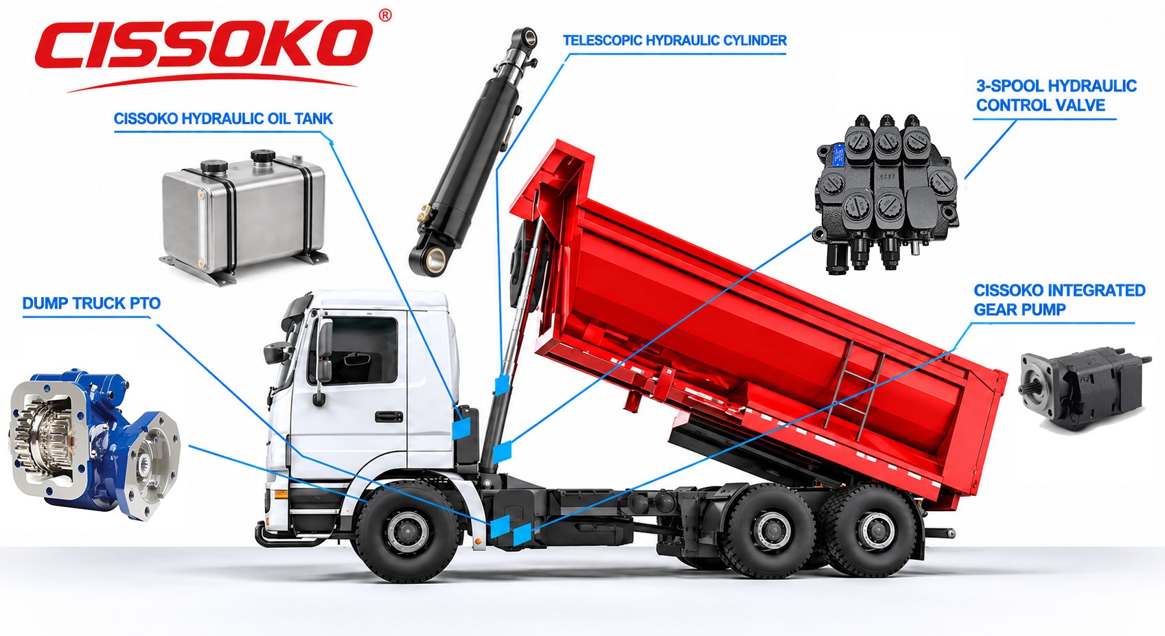
Hydraulic Oil Tank
Telescopic Hydraulic Cylinder
3-Spool Hydraulic control Valve
Dump Truck PTO
Integrated Gear Pump
dump truck hydraulic system turns engine power into lifting force in four steps: PTO drives a hydraulic pump, which pushes oil at 160–210 bar through a control valve into a single-acting telescopic cylinder; the cylinder extends and raises the body on its rear hinge, and gravity brings it back down while a lowering valve holds the descent speed under control.
Pressure is what lifts; flow is what sets the speed. A 200 mm bore cylinder at 200 bar produces roughly 64 tonnes of push.
Most tippers use a single-acting cylinder — oil lifts, gravity lowers. There is no return line doing the work.
70% of "slow lift" complaints come from low oil level, a clogged suction strainer, or a worn pump — not from a failed cylinder.
| Component | Function | Typical spec |
|---|---|---|
| PTO (power take-off) | Takes power from the transmission to drive the pump | Gear-driven or split-shaft, engaged by air or manual lever |
| Hydraulic pump | Converts mechanical power into flow | Gear pump, 60–120 L/min at 1,200–1,600 rpm |
| Control valve | Directs oil to the cylinder and limits pressure | 3-position spool, relief set at 190–210 bar |
| Telescopic cylinder | Converts pressure into lift force | 3–5 stages, single-acting, 130–230 mm bore |
| Reservoir, filter, hoses | Store, clean and deliver oil | 60–150 L tank, 10 µm return filter, 4:1 burst-rated hose |
How the lift actually happens
1. PTO engagement, The driver engages the PTO; the pump starts turning at roughly engine speed through a fixed gear ratio.
2. Suction, The pump draws oil from the tank through a strainer. This is the most neglected part of the system, and also where most cavitation starts.
3. Pressure build-up,Oil enters the control valve. With the spool in "raise," the flow goes to the cylinder base port; the relief valve sits waiting at its setting and never opens during normal lifting.
4. Cylinder extension,Oil fills the lowest, largest stage first. As that stage reaches full stroke, the next stage takes over — the pressure rises step by step and the lift force decreases as the stages get smaller and the cylinder angle leans over.
5. Hinge and body angle, The body pivots on its rear hinge. Typical dump angle is 45–50° for underbody cylinders and up to 55° for front-mounted telescopic units.
6. Lowering, The spool moves to "lower." The pump's flow is redirected back to the tank through the neutral bypass, and the body's own weight pushes the oil out through a restrictor or counterbalance valve so the descent stays controlled instead of slamming down.
The lift is fast; the release is slow. Remember that, and half of your troubleshooting becomes easier.
Front-mounted telescopic cylinder - one multi-stage cylinder sitting ahead of the body, usually under the cab area. Long stroke, high dump angle, best weight distribution, ideal for long bodies and heavy payloads. This is the standard on 8×4 and mining tippers.
Underbody twin cylinder - two single-stage cylinders under the body. Shorter stroke, lower cost, easier maintenance, common on 4×2 and light/medium tippers. The trade-off: with a longer body and heavy load, you get more side-load stress on the body and the hinge pins.
160–210 bar continuous; relief cap 230–250 bar on heavy units.
raise time = cylinder swept volume ÷ pump flow. A 30 L swept volume at 80 L/min gives about 22 seconds - right in the normal 15–25 second window.
keep it under 80 °C; 45–65 °C is healthy. Above 80 °C, oil life halves roughly every 10 °C.
minimum 4:1 burst ratio against the working pressure. A 200 bar system needs hose rated at 800 bar minimum.
Hydraulic cylinders play a vital role in dump trucks, efficiently lifting and tilting the truck bed. Selecting the right hydraulic cylinder is not merely about ensuring compatibility; it is a decision that impacts equipment performance, reliability and service life. An improper choice may lead to low efficiency, higher maintenance costs and even equipment failure.
With a wide range of options available, picking the ideal hydraulic cylinder can be a challenging task. Factors including load capacity, working pressure, material quality and design specifications determine whether the cylinder fits your truck.
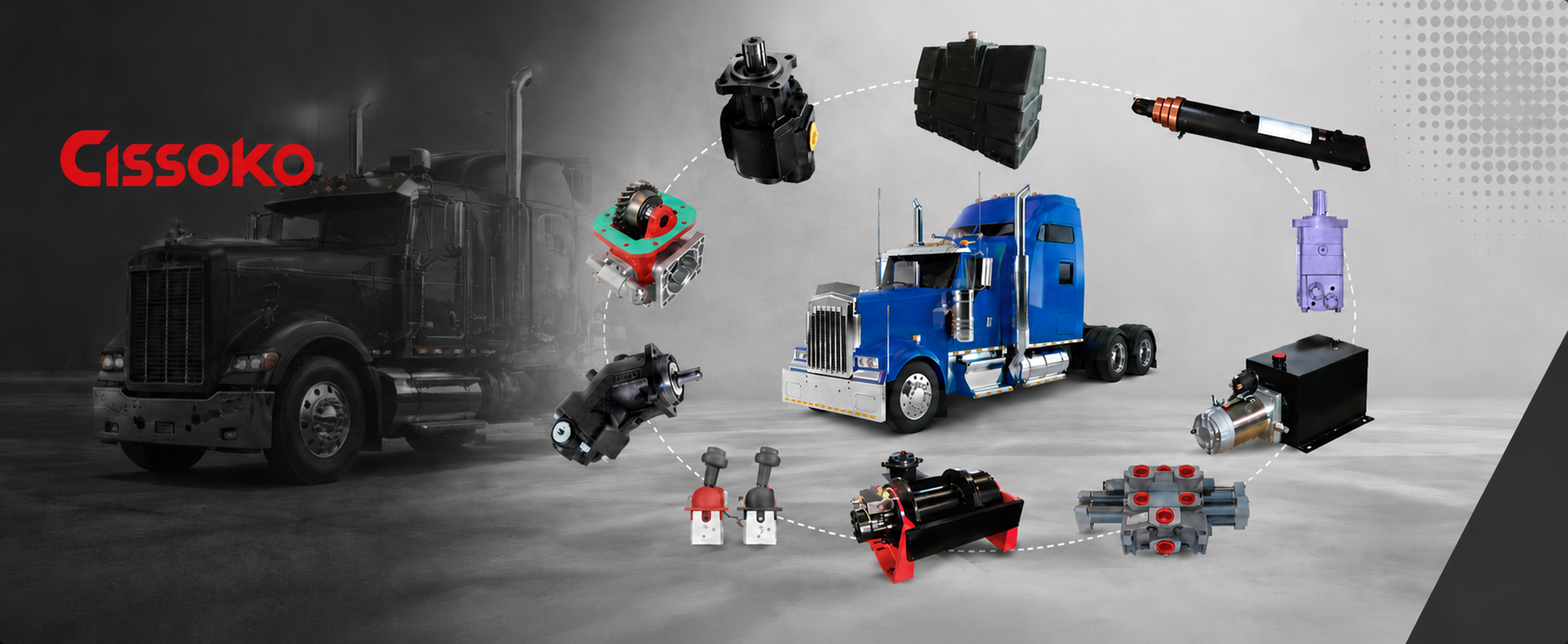
CISSOKO provides reliable hydraulic cylinder solutions for dump trucks, construction machinery, agricultural equipment and other heavy-duty applications. With a focus on product quality, precision manufacturing and customized solutions, we help distributors, wholesalers and equipment manufacturers find hydraulic cylinders that meet their specific operating requirements.
Hydraulic cylinders are manufactured with carefully selected materials and robust structural designs to support demanding working conditions and long-term operation.
We support customized cylinder dimensions, bore sizes, stroke lengths, mounting styles and connection configurations to meet different equipment requirements.
Careful machining and assembly help ensure dimensional accuracy, reliable sealing performance and smooth cylinder operation.
Quality sealing components help reduce oil leakage, maintain hydraulic pressure and improve operational reliability.
CISSOKO hydraulic cylinders are suitable for dump trucks, tipper trucks, construction machinery, agricultural equipment and industrial hydraulic systems.
We work with hydraulic parts distributors, importers, wholesalers and machinery manufacturers, providing product selection assistance and customized supply solutions.

FA6B PTO - CISSOKO

A30 Series PTO - CISSOKO

PTO 281 - CISSOKO

High Efficiency Dump Truck PTO-S NIA

A17 GEAR PUMP OF Rexroth

Gear Pump for Dump Truck

Hydraulic Pumps


